
AODD Pumps
- RELIABLE ENGINEERS
- AODD Pumps
toss pumps
AODD Pumps
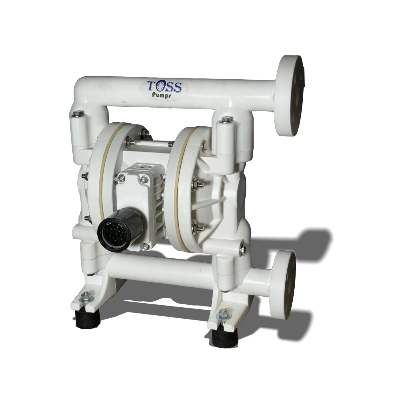
TOSS AODD pumps are self-priming, can handle viscous and abrasive products and can run dry without damage.Additionally, they do not employ costly motors,variable speed drives, by- pass plumbing or mechanical seals.
High Efficiency
Heavy Duty
Adaptability
Less Noise
- The pumps can run dry indefinitely without damage.
- No shaft seals or gland packing.
- Infinitely variable flow & discharge pressure from 0 to pump's maximum by adjusting air pressure. One pump can fit a broad spectrum of applications.
- Gentle non-shearing action.
- If discharge is clogged or closed pump stops immediately; no power consumed, no heat, no wear - By opening discharge, flow starts automatically.
- Operates submerged or with flooded suction.
- Self- priming from a dry start.
- Pressure up to 100 PSI (7 bar).
- No close fitting, sliding or rotating parts so can handle a wide variety of fluids with high solids content.
- Low internal velocity reduces wear.
- Quick assembly and disassembly with split clamp bands.
- Capable of pumping at high temperatures.
- Quiet, steady discharge flow without use of pulsation dampener.
- Safe for use in explosive environments.
- No electrical hazards or costly motor and control equipment needed.
- No pressure relief or bypass.

Submerged
Pumps are totally submersible. It is important that the air exhaust be ported above the level of the fluid,and that the materials of construction also be compatible with the fluid that the pump
is submerged in.
Positive Suction
Pump can draw from the bottom of the vessel. Preferred installation for viscous fluids. For emptying tanks it is important to limit the inlet fluid pressure to approximately 10 PSI(0.69 bar) for Teflon diaphragms and 15 PSI (1.03 bar) for rubber and sentoprene diaphragms.
Self Primining
The suction capabilities of each pump may vary due to system design, product being pumped, and pump materials of construction. Please
consult the factory with specific criteria.
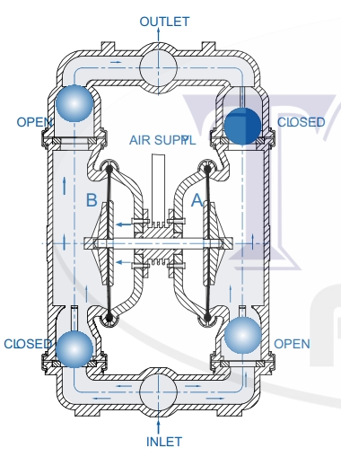
The air valve directs pressurized air to the back side of diaphragm A. The compressed air is applied directly to the liquid column separated by elastomeric diaphragms. The diaphragm acts as a separation membrane between the compressed air and liquid, balancing the load and removing mechanical stress from the diaphragm. The compressed air moves the diaphragm away from the center block of the pump. The opposite diaphragm is pulled in by the shaft connected to the pressurized diaphragm.
Diaphragm B is on its suction stroke; air behind the diaphragm has been forced out to the atmosphere through the exhaust port of the pump. The movement of diaphragm B toward the center block of the pump creates a vacuum within chamber B.Atmospheric pressure forces fluid into the inlet manifold forcing the inlet valve ball off its seat. Liquid is free to move past the inlet valve ball and fill the liquid chamber (see shaded area).
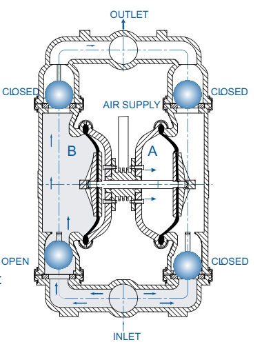
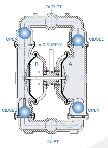
When the pressurized diaphragm, diaphragm A, reaches the limit of its discharge stroke, the air valve redirects pressurized air to the back side of diaphragm B. The pressurized air forces diaphragm B away from the center block while pulling diaphragm A to the center block. Diaphragm B is now on its discharge stroke. Diaphragm B forces the inlet valve ball onto its seat due to the hydraulic forces developed in the liquid chamber and manifold of the pump.
These same hydraulic forces lift the discharge valve ball off its seat, while the opposite discharge valve ball is forced onto its seat, forcing fluid to flow through the pump discharge. The movement of diaphragm A toward the center block of the pump creates a vacuum within liquid chamber A. Atmospheric pressure forces fluid into the inlet manifold of the pump. The inlet valve ball is forced off its seat allowing the fluid being pumped to fill the liquid chamber.
At completion of the stroke, the air valve again redirects air to the back side of diaphragm A, which starts diaphragm B on its exhaust stroke. As the pump reaches its original starting point, each diaphragm has gone through one exhaust and one discharge stroke. This constitutes one complete pumping cycle. The pump may take several cycles to completely prime depending on the conditions of the application.
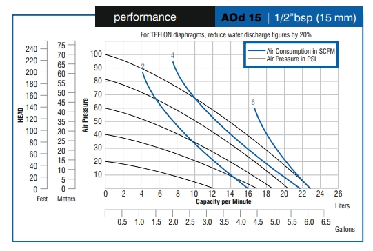
AODD-150
- Mocs Available: PP, PVDF, SS 316, AL
- Max Flow Rate: 40 Lpm (10 gpm)
- Port Size: Inlet: 12.70mm (1/ 2”BSP)
- Discharge: 12.70mm (1/ 2”BSP)
- Air Inlet: 6.35mm (1/ 4”BSP)
- Air Exhaust: 12.70mm (1/ 2”BSP)
- Suction Lift: Dry: 1.45m (4.75')
- Wet: 2.83m (9.28')
- Teflon: Dry: 0.50m (1.64')
- Wet: 0.90m (2.95')
- Max Particle Size (Dia): 2mm (0 .078”)
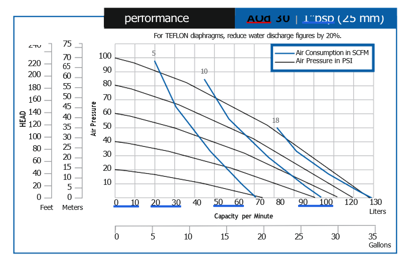
AODD-300
- Mocs Available: PP, PVDF, SS 316, AL
- Max Flow Rate: 135Lpm (34gpm)
- Port Size: Inlet: 25.40mm (1”BSP)
- Discharge: 25.40mm (1”BSP)
- Air Inlet: 9.53mm (3/ 8”BSP)
- Air Exhaust: 12.70mm (1/ 2”BSP)
- Suction Lift: Dry: 3.05m (10')
- Wet: 4.89m (16')
- Teflon: Dry: 2.14m (7')
- Wet: 3.98m (13')
- Max Particle Size (Dia): 3.17mm (0.125”)
AODD-400
- Mocs Available: PP, PVDF, SS 316,AL
- Max Flow Rate: 270Lpm (72gpm)
- Port Size: Inlet: 38.10mm (11/ 2”BSP)
- Discharge: 38.10mm (11/ 2”BSP)
- Air Inlet: 9.64mm (3/ 8”BSP)
- Air Exhaust: 12.70mm (1/ 2”BSP)
- Suction Lift: Dry: 4.57m (15')
- Wet: 7.62m (25') Teflon:
- Dry: 3.05m (10')
- Wet: 6.09m (20')
- Max Particle Size (Dia): 4.76mm (0.188”)

AODD-500
- Mocs Available: PP, PVDF, SS 316, AL
- Max Flow Rate: 586Lpm (155gpm)
- Port Size: Inlet: 50.80mm (2”BSP)
- Discharge: 50.80mm (2”BSP)
- Air Inlet: 12.70mm (1/ 2”BSP)
- Air Exhaust: 19.05mm (3/ 4”BSP)
- Suction Lift: Dry: 4.57m (15')
- Wet: 7.62m (25')
- Teflon: Dry: 3.05m (10')
- Wet: 6.09m (20')
- Max Particle Size (Dia): 6.35mm (0.250”)